Current Projects
Inventor Jay Bailey builds the Skybike
| Rate this project: | (237 votes cast) |
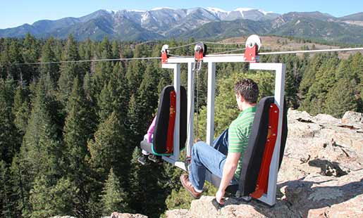
Jay Bailey rides his new "skybike" off the edge of a 125-foot-high cliff with a passenger in the front seat. They soar high over the tops of pine trees while a stream rambles far below. "It's like flying," says Bailey as he pedals the bike along its 450-foot course to the other side of the canyon. "The best seat is in the front; you feel like you're floating through the air with nothing around you."
Bailey designed and built the skybike in his backyard using the PlasmaCAM machine. "The PlasmaCAM system was instrumental in building the skybike," says Bailey. "I thought up the idea and drew the design on my computer. Then I used the machine to make all the challenging parts. I couldn't believe how easy it was, and everything fit together perfectly."
"The PlasmaCAM machine opens up a lot of new possibilities for what you can make," says Bailey. He submitted the following complete story with images showing how he conceived, designed, and built the skybike. At the bottom of the article are links to videos and even a PlasmaCAM drawing file of the invention, provided by Bailey.
The Idea
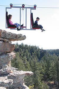
The idea for the skybike came to me when I was buying a piece of land in the Colorado mountains. I stood atop the 125-foot cliff and looked across the vast canyon. I thought to myself, "Wouldn't it be cool to have a cable car that can go straight across that?" Eventually I came up with a design that would be simple and practical to build. I wanted something that two people could ride, that could be pedaled across in either direction. I wanted it open as possible to create the sensation of floating through the air.
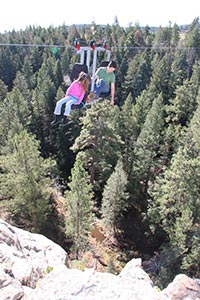
The skybike needed to run a course that was mostly flat so it would feel like you were just riding your bike down the street to the neighbor's house. To do this, the cable needed to operate under tremendous tension. If it broke or the anchors gave way, you would plummet to your death. I came up with a concept for controlling the cable tension. I used hydraulics in a constant tension device with an integral test feature for safety. This allowed me to test the cable and anchors to a higher tension before I put someone on the skybike. If nothing broke during the test tension, then it wasn't likely to break during the operating tension.
Measurements & Calculations
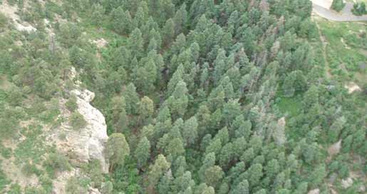
Prior to construction, I identified the best locations for the skybike to land on each side of the canyon and where the ends of the cable would anchor. A prominent cliff on one side made an ideal spot. The other side was sloped more gradually, so I used a transit and GPS to find the location that provided the shortest span and most level elevation for the cable.
I found that the cable would span 450 feet across the canyon. I guessed that the skybike was going to weigh at most 500 pounds with two passengers, so I decided on an operating tension of 14,000 pounds for the cable. From this I calculated that the skybike would sag down 4 feet in the middle of the canyon. I used the PlasmaCAM software to sketch the following full-scale drawing of the terrain and the cable under this maximum deflection:
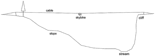
I planned to use a 1/2-inch-diameter stainless steel cable, allowing a 25,000-pound tension test before a ride. A 3-1/2-inch bore, 1-1/4-inch rod hydraulic cylinder could achieve this force with about 3,000 psi. The cable would stretch by as much as 3 feet under this tension, so I planned to use a cylinder with a 3-foot long stroke.
The Skybike
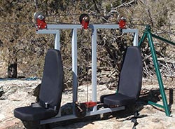
Next I designed and built the skybike itself. I measured bikes, chairs, and an old pedal boat in order to conceptualize the skybike seats and location of the pedals. I cut apart an old bike so I could use the pedals and sprockets. I drew my ideas to size in the PlasmaCAM software. I wanted a simple design that would be easy to build, so I based the design largely on plasma-cut plates. The time spent making these parts was by far the quickest stage of the project. They were cut by the PlasmaCAM machine, cleaned up, and painted. I bent some of the pieces in a brake.
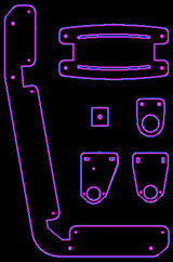
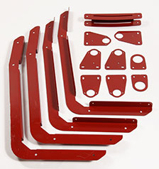
I also used pieces of square tubing cut to length in a band saw, with a few holes drilled in them, and welded together. For the drive system, I bought some sprockets, chain, sealed bearings, and big dowel pins from a parts catalog. The bearings were bolted to plasma-cut plates. Each plate had slotted holes allowing chain tension and alignment to be adjusted. I installed extra bolts in each pulley plate to captivate the cable, so the cable could never come out of the pulleys (leaving passengers stranded). I designed two steel pulleys with V-grooves to maximize traction on the cable. The pulleys, along with a press-fit hub for the small bike sprocket, were parts that I had made by a local machine shop.
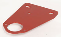
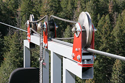
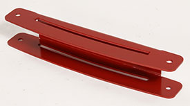 All of the pieces went together well. I didn't have to remake any pieces except for the part shown with the long slots in it; I bent the first piece wrong so I discarded it and made another one in
a couple of minutes. It's nice being able to start over when you mess up a part; you don't feel like you have to salvage the part because you've put so much work into it.
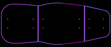
To design and make the seats, I started with standard automotive seat covers. I measured their shapes and drew them in the PlasmaCAM software. From this I designed three plywood pieces to form the structure of each seat. To make the pieces, I plasma-cut their shapes out of thin galvanized steel scrap I had. Then I traced the steel shapes onto plywood with a pen and cut the wood with a jigsaw. I varnished the plywood pieces so they would last longer.
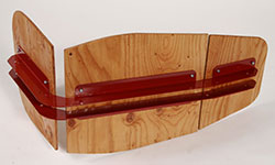
To finish the seats, I bolted the plywood to the metal seat brackets I had made. I bought some 2-inch foam rubber and cut out pieces by tracing the shapes from the metal templates. The seat covers were stretched over the foam rubber and plywood and stapled to the back so everything held tightly together.
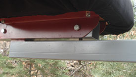
The seats were designed to pivot and reverse easily, for travel in opposite directions. I used shoulder bolts and washers at the pivot points (one at the top and one at the bottom). A single spring pin through the bottom of the frame and seat tube was used to lock each seat into position. To reverse a seat, you simply pull the pin out, rotate the seat, and snap the pin back in.
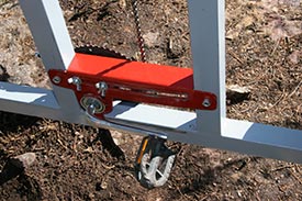
The position of the
pedals can also be adjusted easily to fit different-sized riders and to reverse direction. You simply loosen two wing nuts, slide the pedals into the desired position with your feet, and retighten
the wing nuts. 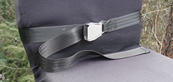 At first I used ropes for seatbelts. Then I located some custom-length seatbelts using the
same buckle that you find on commercial airplanes. Behind each seat, I routed the strap through the slot created between the seat and the frame.
Supports for the Cable
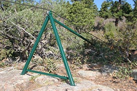
Once the skybike was finished, I knew how high the cable needed to be held above the ground for the skybike to park comfortably at each side of the canyon. I developed cable supports based on tripods with off-the-shelf stainless-steel pulleys at the tops. Most of the tripod feet mounted directly to the exposed bedrock that was available at the sites I had chosen. I drilled into the rock and installed stainless-steel anchor bolts made for concrete. I had to pour a concrete footer for one tripod foot that landed in loose dirt. (This footer also became a convenient place to mount the hydraulic pump.)
Because the terrain was uneven, I measured exactly where each tripod foot would mount to the ground and custom-fit the legs accordingly. To make sure that everything was going to be the right size and shape, I used SolidWorks software program to create 3-dimensional models of the system. It was easy to transfer part designs back and forth between SolidWorks and PlasmaCAM.
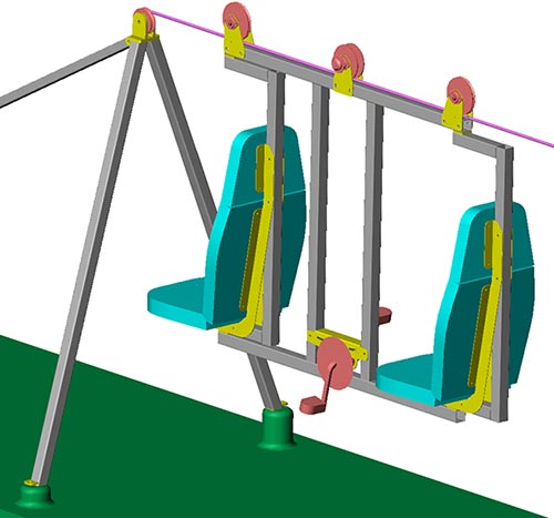
The cable had to withstand up to 25,000 pounds of tension during testing. This meant as much as 5,000 pounds of down force on the tripods, since the cable angled down at the tripods in order to anchor to the ground at the ends. I used 2-inch by 3/16-inch-thick square tubing for the main tripod legs. I designed 1/2-inch-thick plasma-cut plates that welded together and to the tubes, holding the pulleys firmly in position. Smaller plasma-cut plates were used for feet and to cap the bottoms of the tubes. I also welded straps across the bottoms of the tripods to further prevent the main legs from spreading under force.
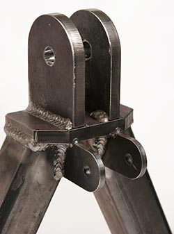
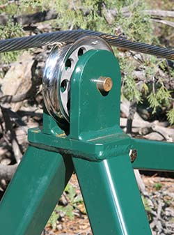
I was really impressed by how perfectly the plates were cut on the PlasmaCAM machine. Again, I found that a lot more work went into measuring and cutting the tubing than making the plates. The rear leg of each tripod was designed to experience less force and to pivot at the bolted joint, making installation and alignment easier. The tripods were powder coated to make them last a long time in the outside weather.
The Cable
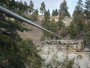
I purchased 500 feet of 1/2-inch diameter cable, just to be on the safe side. The extra 50 feet also made installation easier. I chose stainless-steel cable so I would have less trouble with wear leading to rust.
Getting the cable across the canyon was no small feat, as the entire cable weighed about 250 pounds. First I rolled the spool down to the bottom of the canyon. Next I lowered a 150-foot climbing rope down from the top of the cliff. With the bottom of the rope clamped to the end of the cable, I pulled the rope back up the cliff from the top while the cable was unwound. Then I wrapped and clamped the end of the cable around a tree at the top of the cliff.
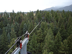
I dragged the other end of the cable back up the slope while the cable was untangled. I wrapped and clamped it around a tree at the top. I used a hand-cable-winch and many pairs of locking pliers to reel in more of the cable to the trees at both sides of the canyon. I attached the climbing rope to the middle of the cable so I could work it up through the trees as it raised. This proved difficult, because the cable got caught in so many tree branches. One tree was especially large and stood right in the final path of where the cable needed to go. With the ends of the cable merely wrapped around the trees, I rode the skybike out to the big tree and sawed the top of it off.
Anchors & Tensioning System
I found galvanized, expanding anchors designed to withstand 35,000 pounds that could be inserted as deep as 5 feet into solid rock. I wanted to install two anchors at each end of the cable for redundant safety. I needed to drill 2-inch-diameter holes, so I rented a portable air compressor with a rock drill and lots of air hose.


I drilled holes into the rock at close to the same angle as the cable. (Otherwise, the forces on the anchor might bend and break its shaft or even rip it through the ground sideways.) Drilling the holes was difficult and took many hours. The rock was so hard on the cliff side of the canyon that I could only drill about 2-1/2 feet into it. On the sloped side, I first had a backhoe dig down to the bedrock, which was 4 feet below ground level. Then I drilled holes 5 feet into the rock.
Probably the riskiest part of building the skybike was getting air to the cliff side of the canyon from the other side, where the air compressor was. Since there was no access to drive to the cliff side, I had to link together many air hoses and string them along the cable like a shower curtain. (The cable had been stretched across the canyon at that time and was tensioned to trees at each side.) I rode the skybike most of the way across the canyon in order to pull the air hoses across, and then I rappelled down from the skybike to the ground by the cliff. I knew that the trees or clamps weren't engineered for this sort of thing and could give out at any time, but I had backup clamps in place that I hoped would stop me once I had dropped about 20 feet. Fortunately, everything held together during this stunt.
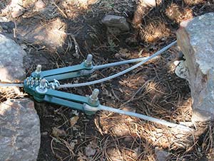
After I installed and tightened the anchors, I had some trouble with them pulling partway out of the holes under the tremendous tension. To solve this problem, I found some high-strength, exterior grout material designed for anchors. I tested it and found that it was unbelievably strong, even when just a small amount was used. I mixed up big batches of it and poured it in behind all of the all the anchors after washing out their holes. This completely filled the cavities for several feet behind each anchor, obstructing any movement.
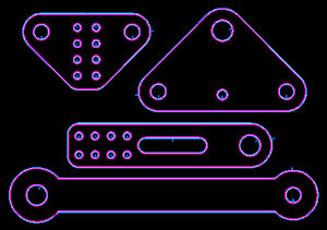
I designed plasma-cut plates to connect the anchors to the cable and tensioning system. One of these plates was cut from 1-inch-thick steel. Again, I was impressed by how quickly I could design and cut perfect parts with the PlasmaCAM system. I had a local machine shop cut V-grooves into the plates that clamped onto the cable, to increase friction. Many bolts were used to clamp these plates together. I even added extra clamps on the cable behind these plates for insurance. Larger bolts were used to link the various pieces together.
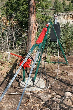
On the sloped side of the canyon, I needed to connect the underground anchors to the tensioning system several feet away. I wrapped 8 strands of 3/16-inch galvanized steel cable around each anchor eyelet and around a large corresponding bolt on the tensioning system. I used three clamps to secure the ends of each cable together. These cables were run through conduit and sealed with lots of silicone to try to keep water out of the underground zone. After everything was finished, dirt was filled back into the large hole.
I built a hydraulic tensioning system using a stock 3,000-psi hand pump and a hydraulic cylinder. The system included a pressure gauge that measures
cable tension, an adjustable pressure-relief valve that regulates the tension, and a ball valve for tension tests. The rod end of the cylinder was connected by a hose to the output of the pump
with the pressure gauge and the pressure relief valve.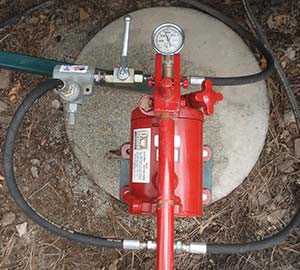 The pressure relief valve allows high-pressure
oil to flow back to the tank. When the ball valve is closed, it blocks this flow. The cap end of the cylinder was connected to the pump's tank by a hose. This handles any oil that might leak past
the seal inside the cylinder, and it also keeps the oil level in the tank from varying as much when the cylinder extends and retracts.
I always do a safety test before using the skybike. I close the ball valve and pump the system to retract the cylinder. I increase the pressure until the cable tension reaches about 25,000 pounds. Then I open the ball valve, allowing the oil to flow through the pressure relief valve until the tension drops to the regulated level of about 16,000 pounds. I don't have to worry about the cable breaking no matter how much weight is on the skybike. As long as the cylinder can extend and release more cable, the tension is always limited to 16,000 pounds. The most important thing is that I have to always remember to open the ball valve.
Video & Extras
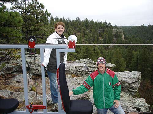
The skybike has become a popular local attraction, and people from all over the country have stopped by to experience an exciting ride.
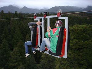
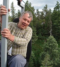
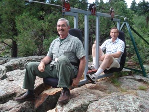
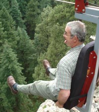
Over time I've discovered more and more uses for the skybike. For instance, simply waving your arms and legs in the right motion makes the skybike bounce up and down for a really wild ride. It can oscillate by 10 feet or more in the middle of the cable, like you're bouncing on a giant trampoline. As you pedal toward one side or the other, the frequency of the bouncing increases. As you reach negative Gs, the skybike begins to twist and jolt violently sideways. (Most people really don't care for this last part.)
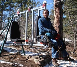
Another fun use of the skybike is for rappelling. You can watch someone rappel down the cliff, or you can rappel directly off of the skybike. This is a great way to enjoy a free-fall rappelling experience.
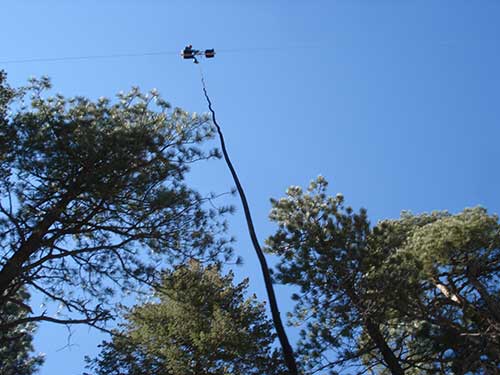
Because the cable slopes slightly downward from the cliff side of the canyon, you don't actually need power to travel across to the sloped side. This creates another opportunity for a thrilling ride; I plan to build a few sets of simple pulleys with handlebars that you can hang onto as you launch yourself off of the cliff. (Of course, I will also have people wear harnesses hooked to the devices in case they let go.) Another device I hope to build is a simple crane that will run on the cable in place of the skybike, for moving heavy objects to and from the canyon floor.
<< Back to Articles

 Click here to get a FREE Demo Video!